
![BE-W[2.0] LITE Wall Box 1 Socket Type 2](http://scamesolutions.com.au/cdn/shop/files/205w119b_1.jpg?v=1737525565&width=800)


SCAME Isolator Switch 20A 3P+SN IP66/IP69 — Emergency
Tax included. Shipping calculated at checkout
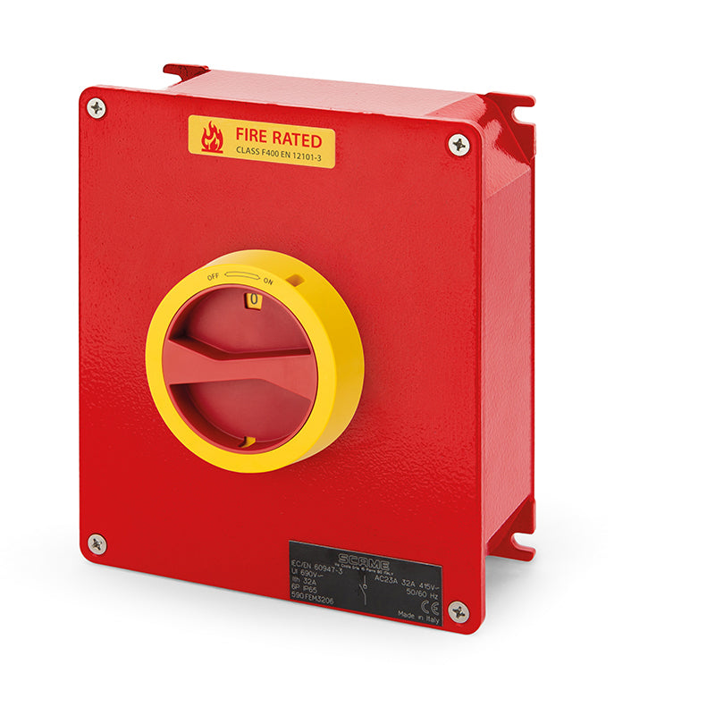
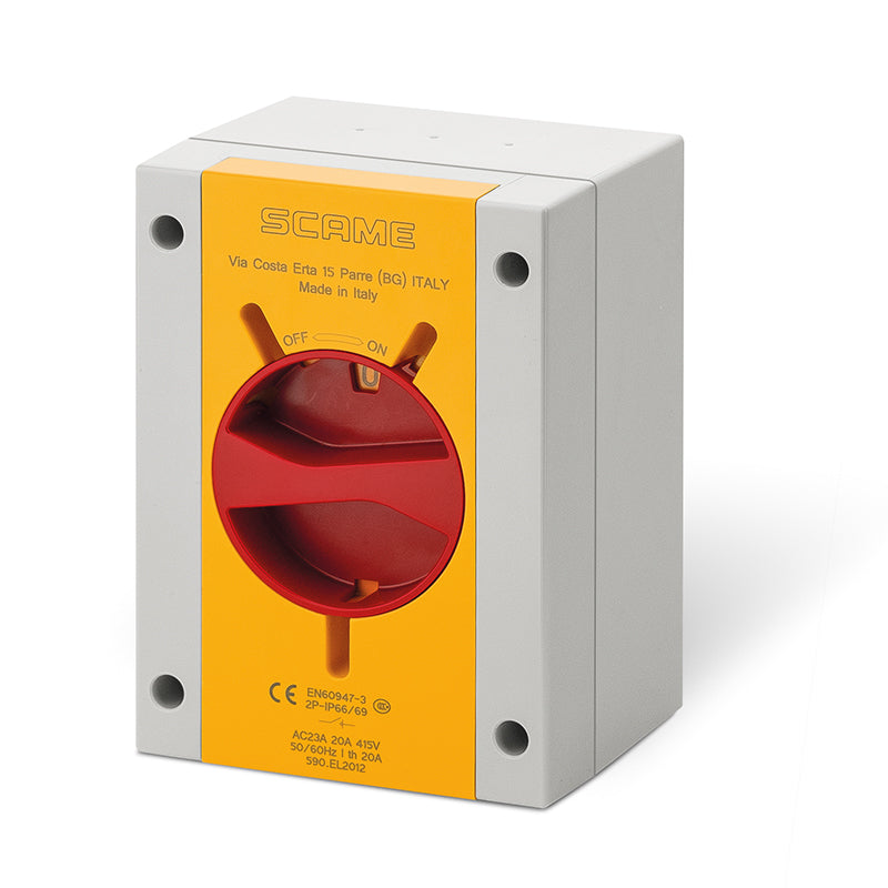
The ISOLATORS-TP Series switch disconnector is purpose-built for general industrial and commercial applications requiring reliable load isolation and enhanced operator safety. Constructed from robust engineering plastic, this enclosed surface-mount isolator provides exceptional durability and ingress protection, rated IP66/IP69 and IK09 for impact resistance.
Its high-visibility yellow/red handle supports lockout capability in both the OFF (up to three padlocks) and ON (one padlock) positions, ensuring compliance with safety lockout procedures. The unit includes a neutral link (SN), reversible base, and door interlock for added installation flexibility and protection.
Designed for dependable performance, it operates at a rated current of 20A (AC23A at 415 V), supports up to 690 VAC insulation voltage, and delivers reliable isolation in demanding environments. Ideal for HVAC systems, motor control, and general power isolation.
Key Features
-
Rated Current: 20 A (AC23A 415 V)
-
Poles: 3P + N LINK (with neutral link)
-
Enclosure: Engineering plastic, surface-mount
-
Protection: IP66/IP69, IK09 impact rating
-
Switch Size: Y1
-
Handle: Yellow/Red, padlockable (OFF 3 × / ON 1 × padlocks)
-
Interlock: Door interlock for safety
-
Base: Reversible with pre-marked drilling points
-
Dimensions: 110 × 150 × 87 mm
-
Temperature Range: −25 °C to +60 °C
-
Glow Wire Test: GW 650 °C
-
Short-Time Current (1 s): 400 A
-
Conditional Short Circuit: 10 kA eff (gG 20 A fuse)
Eligible for Free Shipping Australia Wide on orders above AU$249
*Excludes Large and Bulky Items
Product specifications
YOUR SELECTED MODEL
590.EM2015.SN
The specifications below belong to this product. Use them to confirm the current, pole configuration, protection rating and enclosure dimensions required for your installation.
Download datasheet
ISOLATORS-TP
Built for demanding installations
From compact machine isolation to high-current switching, the ISOLATORS-TP range brings together a tough thermoplastic enclosure, a clear operating handle and practical wiring access.
Choose from general-use and emergency-use versions across the 16A–250A catalogue range, with pole configurations to suit the installation.
Protection matched to the model. Standard surface enclosures offer IP66/IP69; K2 hinged-door models are IP65. Other configurations have different ratings—refer to this product’s specifications.

ISOLATORS-TP IN ACTION
A closer look at the range
See the ISOLATORS-TP design in action, from the recessed, high-visibility operating handle to the practical enclosure details.
The range combines protected control, accessible wiring space and flexible mounting options for industrial installations.

MAIN CHARACTERISTICS
Designed around the details
01 · Door locking with handle in the ON position
02 · Recessed XXL handle to prevent breakage due to accidental impacts
03 · AC23 switch with the possibility of double auxiliary contact
04 · Handle padlockable in the OFF position (emergency use) and ON and OFF positions (general use)
05 · High visibility handle and plate
06 · Knockout cable entries
07 · Reversible base
08 · External and integrated fixing points
09 · Blank side with drilling point marks
Characteristics shown apply to the standard surface-mounting version illustrated. K2 hinged-door models have blank cable-entry sides and lock in the OFF position only.
SELECT THE RIGHT VERSION
More room when wiring demands it
Standard surface mounting
Compact thermoplastic enclosures with Class II double insulation. Standard 20A–100A versions provide IK09 impact resistance; 125A–160A surface versions are IK08.
High wiring capacity · .W
The same switch in the next enclosure size up gives larger cable radii and more internal wiring space. Select the .W version where additional room is needed.
PLAN YOUR INSTALLATION
Choose with confidence
Understand the part number, check the environment and plan your cable entries.
How to read a part number
590.GE·63·05·.SN
590.
Prefix
SCAME article
GE
Version
GE = general use
EM = emergency use
EL = special high visibility
CGE / CEM = EMC connection
GR / ER = OMNIA flush mounting
63
Current
16 to 250
amps (AC22A, 415V)
05
Poles
02 / 12 = 2P
03 / 13 = 3P
05 / 15 = 4P (3P+N)
06 = 6P 08 = 8P
22 = 1P+SN (Y01)
12 / 13 / 15 identify size Y1 and the 160A K2.
.SN
Suffix
.SN unswitched neutral — solid neutral terminal block
.W high wiring capacity (.WSN combined)
-P 40A Y1-P performance switch, 22kW
Emergency vs General handleColours & locking positions
The GE and EM versions use different handle colours and padlocking arrangements. Match the version to your installation requirements.
| Feature | General use · GE | Emergency use · EM |
|---|---|---|
| Handle & plate | Black handle with grey plate | Red handle with yellow plate for high visibility |
| Standard versions: OFF locking | Up to 3 padlocks | Up to 3 padlocks |
| Standard versions: ON locking | 1 padlock | Not padlockable in ON |
| K2 hinged-door versions | OFF locking only, up to 3 padlocks | OFF locking only, up to 3 padlocks |
Both versions have door locking with the switch in the ON position. This enclosure interlock is separate from padlocking the operating handle. Check the selected model's datasheet for its ratings and configuration.
Auxiliary contactsMatch your switch size
Match the accessory to the switch size—not just the current rating. Up to two auxiliary contacts can be fitted per switch. Contact our team to confirm the contact arrangement and availability.
| Switch size | Part number & description |
|---|---|
| Y1 · 20A–40A | 590.PL004005 |
| Y2 · 63A–80A | 590.PL004006 |
| Y3 · Y4 · Y5 | 590.PL005 |
| K2 · hinged door | 590.PL006011 / 590.PL006021 |
Chemical & atmospheric resistanceCheck the environment
SCAME's indicative guide for the thermoplastic enclosure.
Application guidance: SCAME states that chemical-resistance values are indicative. For specific substances and application conditions, contact our technical team before selecting the enclosure.
Cable-entry & enclosure guidePlan the wiring
Match the enclosure dimensions on your product datasheet to the table below. High-wiring-capacity versions use a larger enclosure, so select by dimensions rather than current alone.
| Enclosure dimensions | Top | Bottom | Rear |
|---|---|---|---|
| 82 × 120 × 69 | 1 × M20 + 1 × M25 knock-outs | 1 × M20 + 1 × M25 knock-outs | 2 × M20 knock-outs |
| 110 × 150 × 87 / 96 | 2 × M25 max + 1 × M32 max drilling points | 2 × M25 knock-outs | 1 × M25 knock-out + 2 × M25 max drilling points |
| 160 × 220 × 115 | 3 × M40 max drilling points | 2 × M32 knock-outs | 1 × M32 knock-out + 2 × M32 max drilling points |
| 240 × 340 × 137 | 2 × M63 max + 1 × M16 max drilling points | 2 × M50 + 1 × M16 knock-outs | 1 × M50 knock-out + 2 × M50 max drilling points |
| 308 × 388 × 128 | Blank | Blank | Blank |
| 460 × 520 × 245 (K2) | Blank | Blank | Blank |
Knock-outs and drilling points describe the enclosure provision; they do not indicate supplied cable glands. Blank faces require cable-entry preparation. Confirm the exact model before drilling.
Source: SCAME ISOLATORS-TP leaflet ZP01352-EN-0. Ordering: pp. 2–9; chemical resistance: pp. 20 & 23; cable entries: pp. 20 & 24.

Scame Electrical Solutions Australia Pty Ltd
ABN 65 168 757 542
Tel: +61 (08) 9248 4445
sales@scame.com.au
8 Masonry Way, Malaga, WA 6090